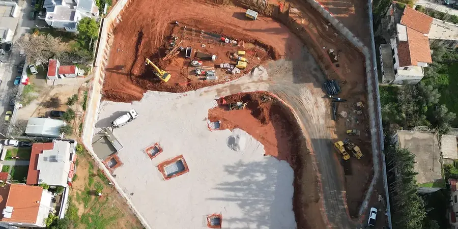
In Northampton, you learn quickly that the geology doesn't read the textbooks. We've seen jobs where the ironstone beds in the Northampton Sand Formation appear three metres higher than the borehole logs suggested, and suddenly your temporary works need rethinking. That local variability is what makes CPT testing so valuable here before any cut exceeds 2.5 metres. The town sits on a sequence that transitions from Northampton Sand into the underlying Lias Clay, and in the Nene valley you hit alluvium and river terrace deposits that complicate groundwater control. A deep excavation in the town centre near the Guildhall faces completely different ground than one out by Brackmills. You need a design that respects those transitions, not a generic section copied from a manual. Our approach ties every prop level, berm width, and dewatering trigger to ground conditions we've verified through targeted investigation and in-situ permeability testing in the actual strata you'll be excavating.
A Northampton excavation design that ignores ironstone joint orientation or Lias Clay swell pressure is a programme risk waiting to happen.
Process overview
Local context
BS EN 1997-1:2004, applied through the UK National Annex with Design Approach 1, puts a specific duty on the designer to define limit states for each phase of the dig. In Northampton, the risk profile is dominated by three factors. First, the ironstone's blocky joint structure: a wedge failure in a temporary slope can propagate faster than any monitoring system can alarm. Second, the Lias Clay's strain-softening behaviour means a serviceable wall in week one can develop excessive deflections by week six if prop preload is lost due to thermal effects or poor workmanship. Third, groundwater in the Nene gravels is tidally influenced during high river stages; a design that assumes a static water level is unsafe. We build these risks into the Observational Method framework, with contingency triggers written into the construction sequence before the first bucket comes out.
Reference standards
BS EN 1997-1:2004 (Eurocode 7: Geotechnical design — General rules), BS EN 1997-2:2007 (Ground investigation and testing), BS 5930:2015 (Code of practice for ground investigations), BS 8002:2015 (Code of practice for earth retaining structures), CIRIA C760 (Guidance on embedded retaining wall design)
Additional services
Temporary Works Design for Deep Excavations
Full design of propped and anchored retaining systems for basements, shafts, and cut-and-cover structures. We produce CAT III checked designs with staged excavation sequences, strut and waler schedules, dewatering specifications, and movement predictions. Every design includes a site-specific geotechnical interpretative report tied to the actual strata logged in Northampton.
Excavation Monitoring Plans and Review
We write instrumented monitoring plans that define trigger values for tilt, settlement, and piezometric response, aligned with the Observational Method under CIRIA C760. We also provide ongoing review of monitoring data against design assumptions during construction, with rapid re-assessment if conditions diverge from the ground model.
Typical parameters
Top questions
What does deep excavation design typically cost for a project in Northampton?
For a design package covering temporary works for a single basement or shaft in Northampton, fees generally range from £1,600 for a straightforward propped excavation in competent ironstone to £7,090 for a complex multi-level dig in the Nene valley with groundwater cut-off, staged dewatering, and full CAT III checking. The spread reflects the ground variability across town — a Brackmills job in dry Lias is at the lower end; a town-centre excavation with artesian risk is at the higher end.
How do you handle the transition between Northampton Sand and Lias Clay in a single excavation?
The interface is rarely flat — it can undulate several metres across a site footprint. We model the geometry from closely spaced boreholes or CPTs, then design the support system for the weaker of the two materials at any given elevation. In practice this often means extending sheet pile toes deeper than a pure sand design would require, and checking basal heave in the Lias assuming fully softened strength parameters.
What monitoring do you specify during an excavation in Northampton?
At minimum: inclinometers behind the retaining wall, optical prisms on the wall face and adjacent buildings, settlement points on buried services, and standpipe or vibrating-wire piezometers at key horizons. For excavations over 6 metres deep, we typically add load cells on selected props and crack-width gauges on any listed structures within the zone of influence. Trigger levels are set as a percentage of predicted movements, with amber and red thresholds tied to specific review actions.