BS EN 1997-1:2004 and the UK National Annex require detailed Improvement design for any structure founded on granular soils with relative density below 65%. In Northampton, where the Northampton Sand Formation and Nene River gravels create pockets of loose, water-bearing ground across the town centre and expanding suburbs like Upton and Grange Park, vibrocompaction design becomes a critical step before construction. Our team develops site-specific vibrocompaction schemes that account for the iron-rich sandstone bands and variable alluvial deposits found across the 52.2343 latitude corridor. The design process integrates in-situ test data from spt-drilling to establish pre-treatment density profiles, then specifies probe spacing, grid geometry, and energy input per compaction point. For sites near the Nene floodplain where the water table sits just 1.5 metres below surface, we incorporate backfill specifications that prevent water ingress during deep compaction. Every design package includes performance criteria tied to post-treatment verification, typically requiring a minimum relative density of 70% or a cone resistance above 15 MPa, whichever governs. This approach has proven effective across Northampton’s industrial estates and residential developments where loose made ground overlies competent bedrock at depths between 4 and 12 metres.
In Northampton’s ironstone terrain, vibrocompaction without a site-specific design is just rearranging the problem—proper compaction point geometry and energy specification are what separate densification from disturbance.
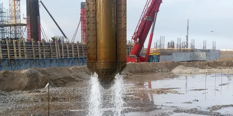
Process overview
Local context
One pattern we consistently observe on Northampton sites is that historical fill—particularly in the St James and Semilong areas—was placed without controlled compaction, creating a crust of firm ground over very loose material beneath. A vibrocompaction design that treats the whole profile uniformly will leave these deeper pockets untouched because the probe encounters high resistance in the crust and the operator moves on. Our designs flag these zones explicitly, requiring pre-drilling or extended dwell time at specific depths. Another practical concern is the proximity of neighbouring structures in Northampton’s terraced streets; we routinely include peak particle velocity limits in the specification—typically 5 mm/s at the nearest foundation—to prevent vibration damage claims. The ironstone bands present a different risk: they can deflect the vibroflot off vertical, so our designs include a verticality tolerance of 1:50 and recommend real-time monitoring of probe inclination. When the water table is high, as it often is within 800 metres of the Nene, incomplete compaction below the phreatic surface is a real possibility unless the design explicitly accounts for pore pressure dissipation between passes.
Reference standards
BS EN 1997-1:2004 (Eurocode 7: Geotechnical design – General rules), BS 5930:2015 (Code of practice for ground investigations), BS EN 14731:2005 (Execution of special geotechnical works – Ground treatment by deep vibration), ICE Specification for Ground Treatment (current edition)
Additional services
Feasibility assessment and ground model
Review of existing borehole data, SPT blow counts, and particle size distributions to confirm vibrocompaction suitability. We flag zones where stone columns or dynamic replacement may be more appropriate, particularly in Northampton’s silty alluvial deposits near the Nene.
Detailed compaction point layout and specification
Production of grid plans showing probe locations, target depths, energy input per point, and backfill type. Includes phasing diagrams for sites where vibration-sensitive neighbours require a sequenced approach.
Pre-treatment CPT or SPT verification programme
Design of the pre-treatment testing layout to establish baseline density profiles. We specify test locations that capture the variability of the Northampton Sand Formation and any made ground inclusions.
Post-treatment validation and sign-off
Interpretation of post-compaction SPT or CPT results against design acceptance criteria. We provide a formal statement of compliance referencing the BS EN 1997 design assumptions and confirming the treated ground meets the specified performance parameters.
Typical parameters
Top questions
What does a vibrocompaction design package cost for a typical Northampton plot?
For a standard residential or light commercial plot in Northampton, a complete vibrocompaction design package—including ground model review, compaction point layout, specification, and post-treatment verification criteria—ranges from £1,300 to £3,650 depending on site area and the complexity of the ground conditions. Sites requiring additional pre-treatment CPT testing or detailed vibration impact assessments at neighbouring properties fall toward the upper end of that range.
How do you determine whether vibrocompaction will work on a Northampton site?
The primary screening criterion is the fines content of the granular soil: if more than 15% of the material passes the 63-micron sieve, vibrocompaction alone is unlikely to achieve the required density. We review particle size distribution curves from trial pits or boreholes, along with SPT N-values. Sites in Northampton underlain by clean Northampton Sand or Nene gravels are usually excellent candidates, whereas silty alluvial deposits near the floodplain often require a combined approach or an alternative technique like stone columns.
Do you handle the site supervision during vibrocompaction execution?
We provide the design and verification package, and we can arrange for an experienced geotechnical engineer to attend site during the first day of compaction to confirm that the probe penetration rates and energy draw match the design assumptions. Full-time supervision is available as an additional service, which some Northampton clients request when working near sensitive structures or when the ground conditions depart significantly from the investigation data.